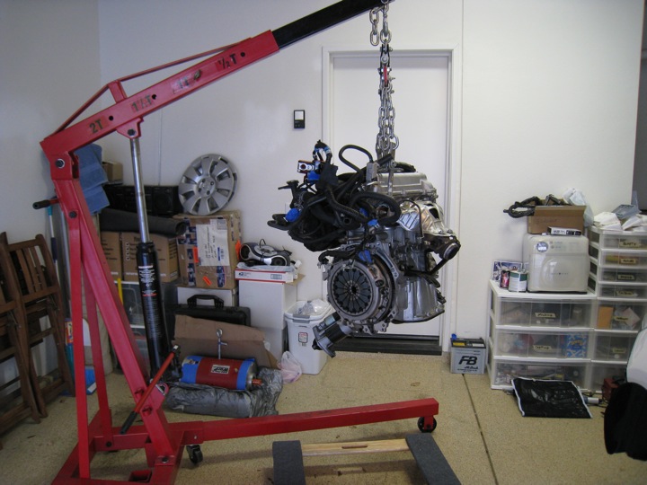
Despite hitting a snag with the drive shafts, I proceeded with a plan to drop the transmission out of the engine bay (gently resting it on the floor) while using the hoist to lift the engine up and out.
I started by installing the factory engine hooks to the proper locations and rigging up the engine hoist and leveler. With the chains taught, I removed the load of the engine from the mounts and proceeded to unbolt the transmission and all of the motor mounts. A bit of wrestling to get the flywheel and clutch clear of the transmission bell housing and I had it free. However, at this point the 'engine control rod' as it's called in the repair manual had escaped me and was preventing the transmission from dropping out. Once I unfastened that, I won.

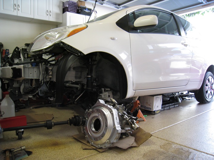
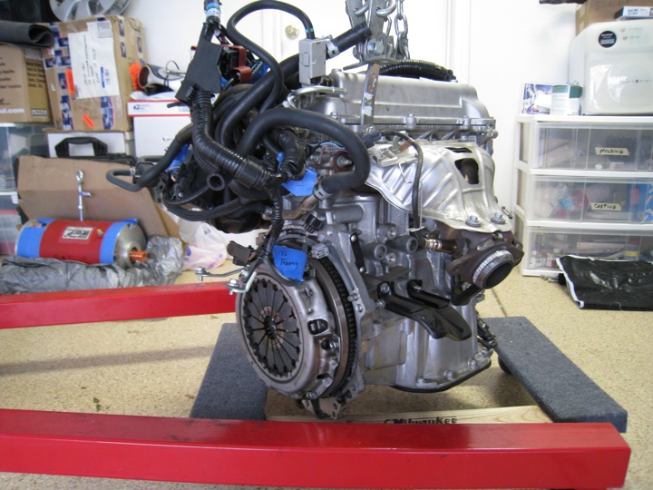
Here's a closer look at the Yaris engine lowered onto a furniture dolly. I read that this thing only weighs 180 lbs.

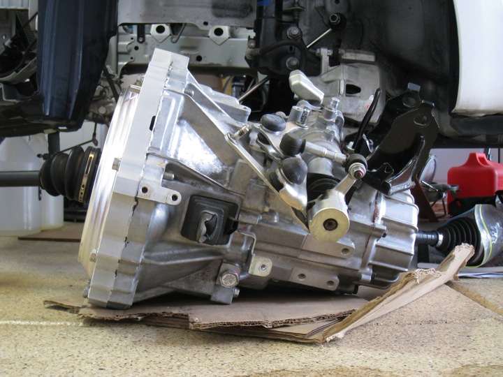
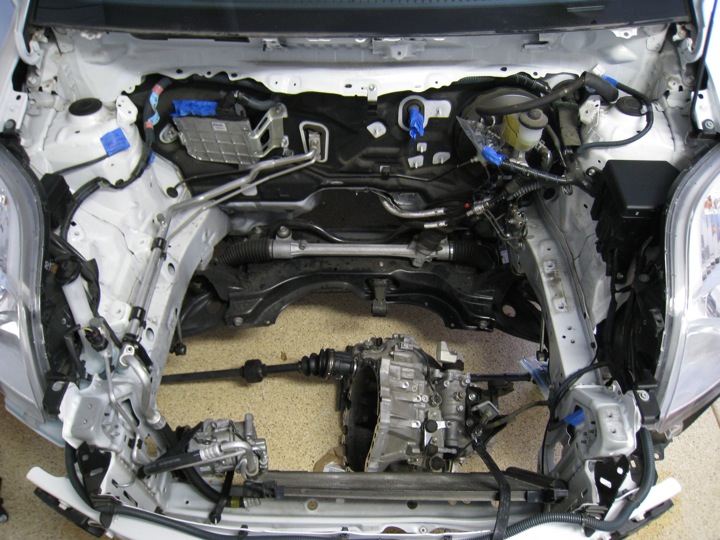
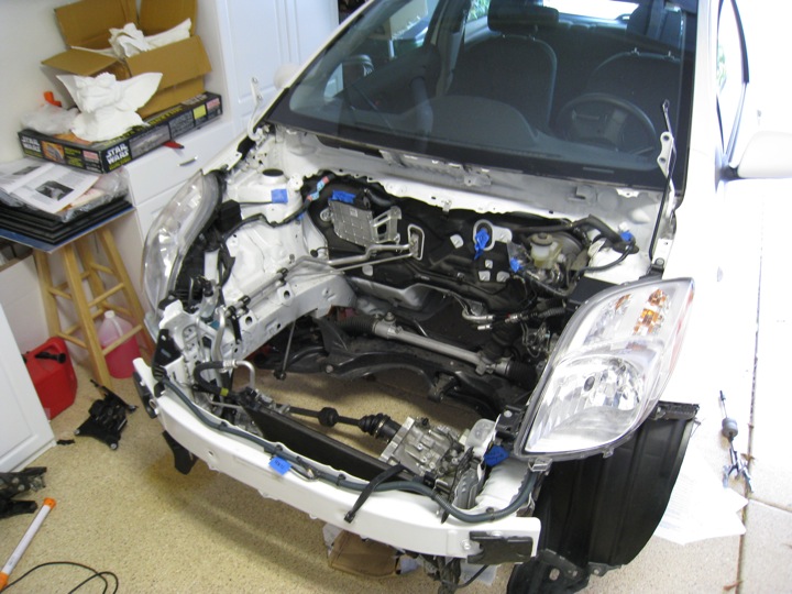
Still in need of a cleaning (but hardly dirty), the engine bay looks great. The transmission looks a little small in this photo because it's sitting on the floor about a foot from where it should be.


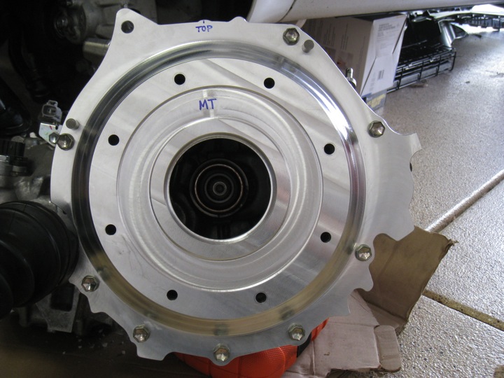
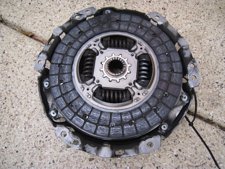
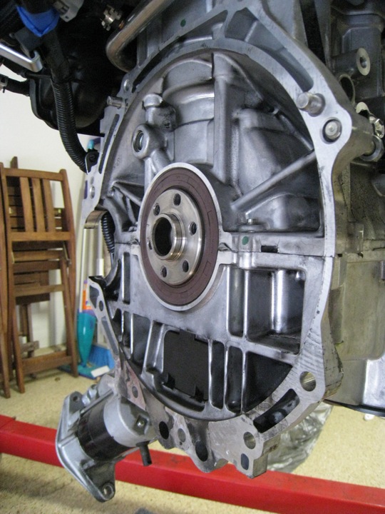
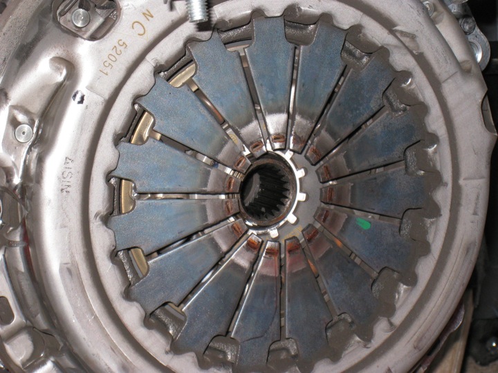
Below is a close up of the clutch assembly. Note that there is no pilot bearing to connect the flywheel hub to the the splined shaft coming from the transmission.

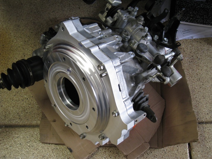
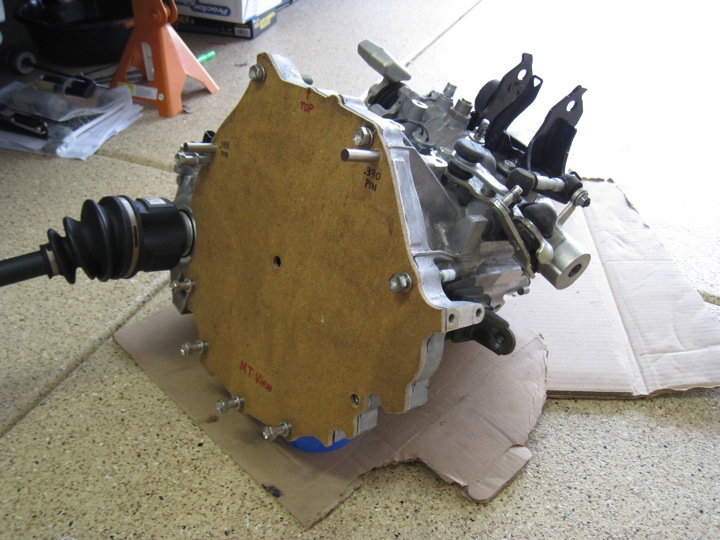
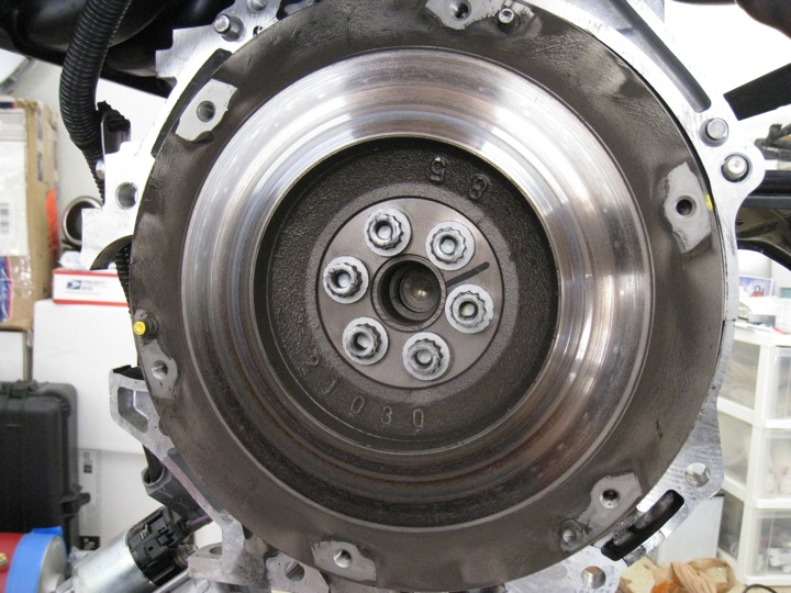
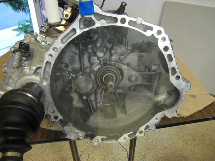
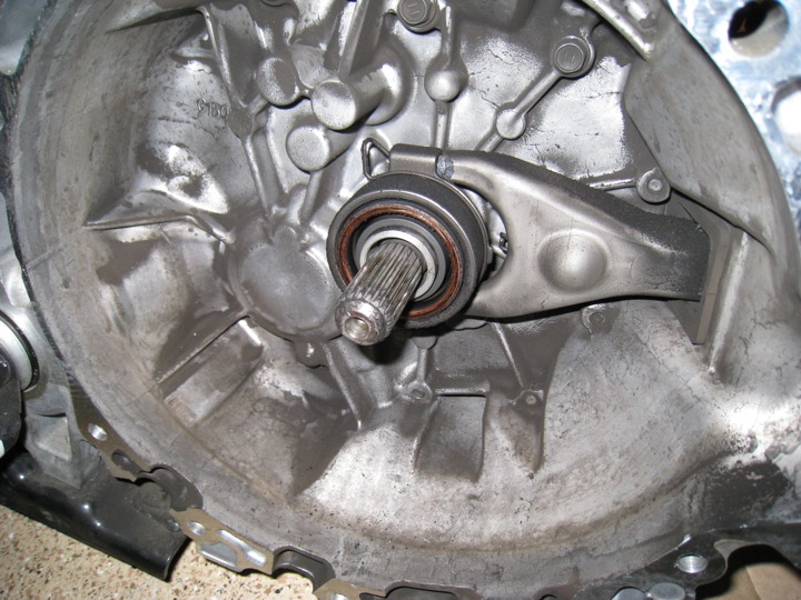
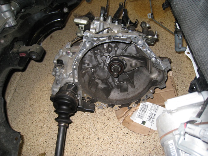
With the engine and transmission separated, I can finally get a good look at the splined input shaft, throw out bearing, clutch fork, and of course... the bell housing flange .


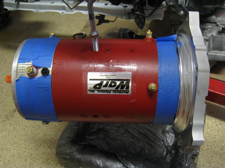
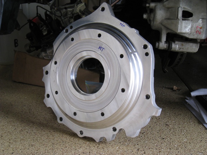
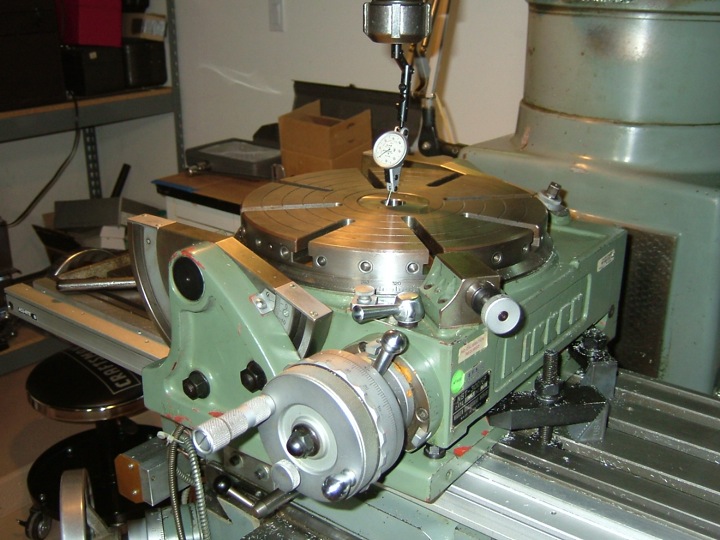
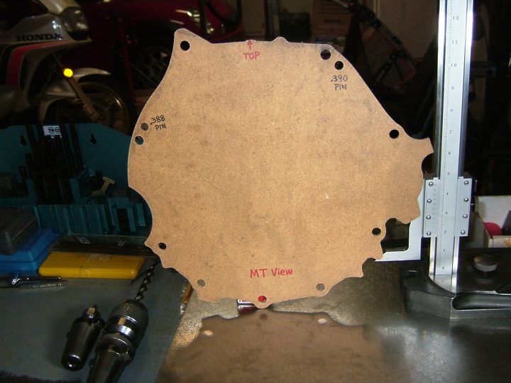
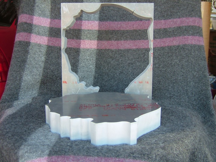
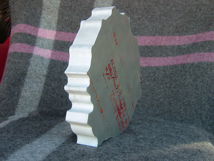
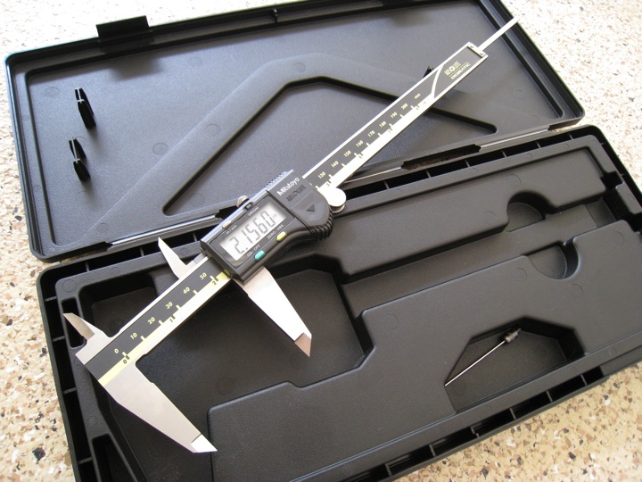
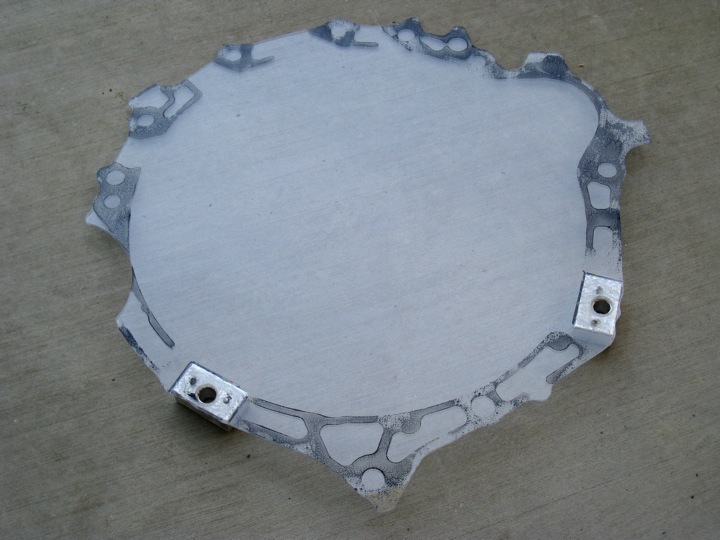
Next up, it's time to start planning and measuring. The design of the adapter plate to mount the Warp 9 electric motor to this transmission is critical. All the part have to line up just right to ensure proper operation as well as safety and reliability.
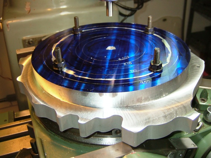
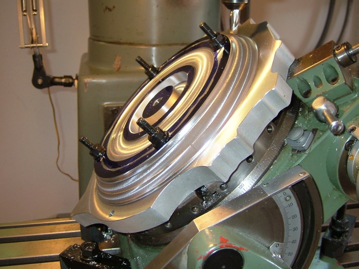
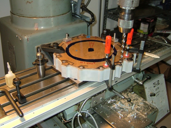
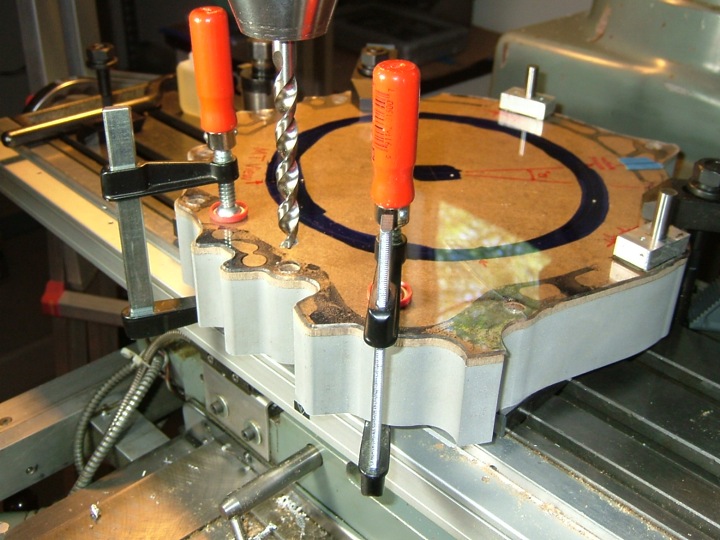
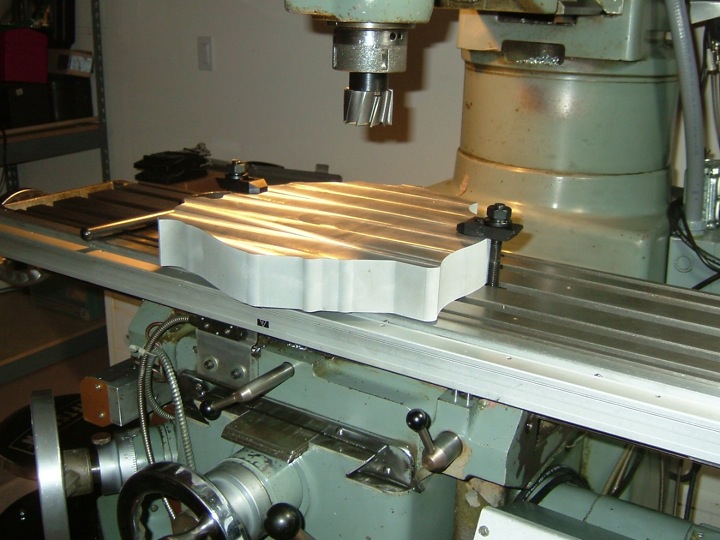
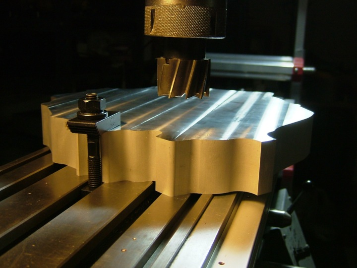
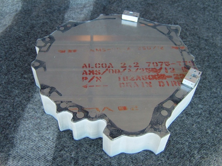
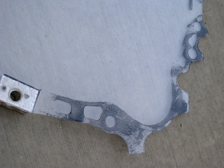
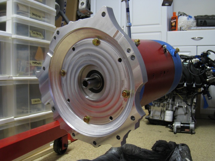 Below is a view of from the top of the motor looking down. You can see the tapered section of the adapter plate significantly reduces the overall mass. Everything is lining up properly. Once I have the hub in hand, I can attach the flywheel and clutch assembly to the electric motor's shaft and test the fit/clearance of the last critical mechanical drivetrain pieces.