Monday, February 21, 2011

Back at it!

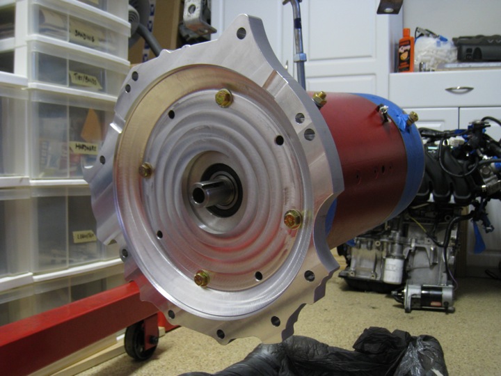
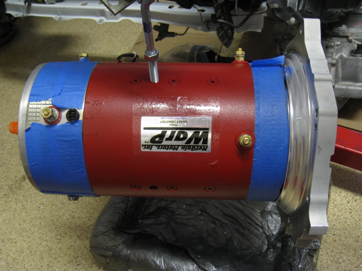
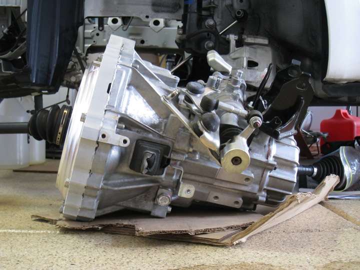
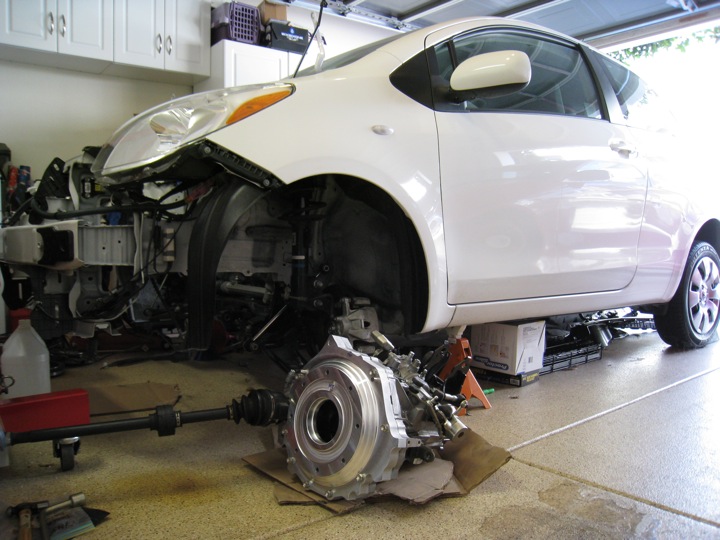
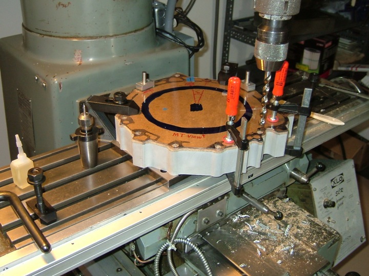
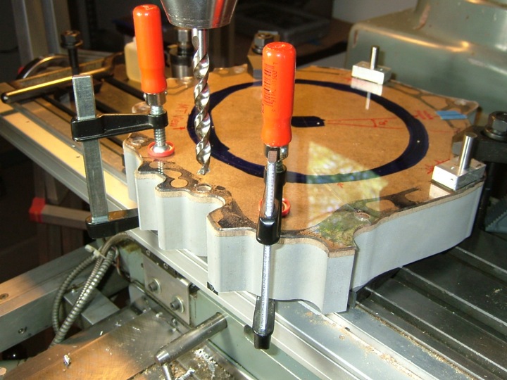
Work got really busy and I didn't have time to devote to my EV project. I'm extremely happy that I've been able to get back to work on the Yaris. This update will be brief. I spent this weekend doing some measuring, planning, and finally a test fit of the motor mounted to the transmission IN THE CAR. That's right, I temporarily got the drivetrain in place to make some last minute decisions on the CE motor mount design and it was a bear of a task.
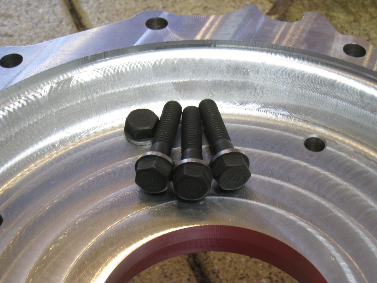
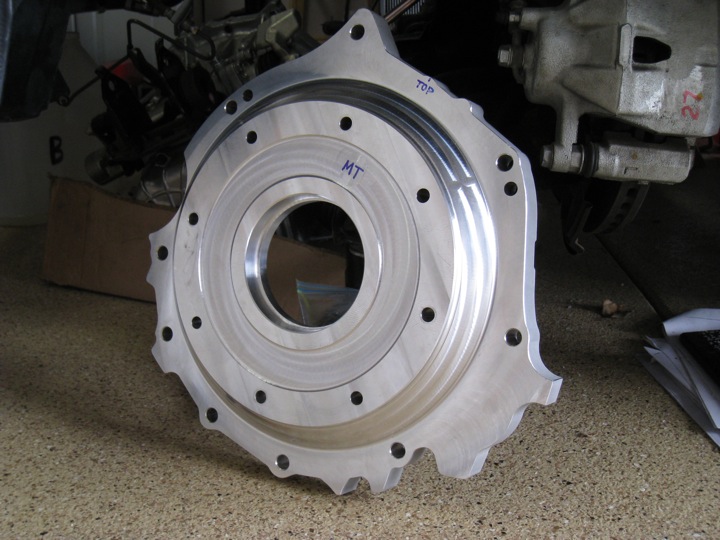
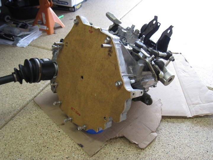
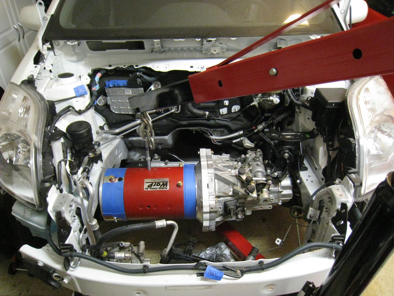
It's a really tight fit to say the least, and that made it really tricky to get this thing bolted up to the transmission. I will be tearing it down again shortly, but I wanted to get a shot of it since it was a pretty big deal to me. Oh, and below I snapped a quick photo of the correct bolts machined to mount the adapter plate to the Warp 9 motor. Notice the washer-like flange is custom turned:

Sunday, September 27, 2009

Does it fit the motor?

While I wasn't able to find the exact bolts I was looking for (these are 1/4" too short), they were long enough to check the mounting hole locations. Once again, the fit was great. I had picked up washers to use with the bolts but their outer diameter is just a hair too big. I will try to purchase flanged bolts which will make this a non-issue.
Below is a view of from the top of the motor looking down. You can see the tapered section of the adapter plate significantly reduces the overall mass. Everything is lining up properly. Once I have the hub in hand, I can attach the flywheel and clutch assembly to the electric motor's shaft and test the fit/clearance of the last critical mechanical drivetrain pieces.

Try it on for size

I popped into the garage this morning to test fit the adapter plate to the transmission first (since I already had the OEM bolts on hand). Everything lined up great. Here are two photos of the test fit:
Temporary alignment pins were gently tapped into the transmission with a small hammer until they seated properly. Next, I threaded all the bolts at the bottom and inserted the longer bolts through the holes in the top of the transmission. These will require nuts and washers on the back side. Below you can see the input shaft is well centered with the motor-side pilot hole, indicating a good alignment.
This photo puts the scale of the tiny transmission into perspective. Especially considering how small a Yaris is. Speaking of small, the adapter plate weighs in at just under 12 lbs. Despite being machined from a solid piece of aluminum, the finished piece turned out relatively light.
Next up, test fitting the adapter plate to the Warp9 motor.

Thursday, September 24, 2009

Sunday Sunday Sunday!

I received the motor adapter plate from my father (who lives in Arizona). He did an excellent job machining this and it was great working on this piece together via iChat, telephone calls, and email. I appreciate all the time and hard work he put into fabricating it. Sunday is the day I'll get to test fit it to the transmission and Warp9 motor. I need to pick up some proper bolts to make sure everything is aligned as it should be.

I am really anxious to get this thing put back together. Until then, here is a picture of the completed piece sitting next to the Yaris in the garage.

Monday, September 7, 2009

Fabrication: Adapter Plate (part IV)

Here's an in-progress photo of the adapter being machined. At this point some dimensions have been laid out on the electric motor face. The holes for the four bolts that secure the motor to the adapter are already drilled. Also, you can see material has been removed along the profile revealing a 1" thick flange (the piece started out 2" thick).
In this next image, you can see the whole adapter (mounted to a rotary table) angled so that a conical taper can be machined from the 1" thick flange up to the face the motor will mount to. The entire aluminum piece gets rotated as the mill cutter turns in place.
The rotary table is a heavy duty piece of equipment. Also pictured in the photo below is a dial indicator used to ensure the part being machined on the mill is perfectly flat. It can measure extremely minute changes in height as the part is moved/rotated under it.

Saturday, August 15, 2009

Measure twice, cut once

When the Masonite template arrived, I quickly mounted it to the transmission with the help of some steel alignment pins and the OEM bolts used to attach the engine. I found that there are 9 holes in the transmission (we also put 9 holes in the adapter template) but only 8 bolts were used on this particular car. So I'm short a bolt if I want to take advantage of all the holes.
The holes along the bottom were slightly offset. This is the point of checking the measurements with this template before cutting an expensive piece of aluminum. 4 of them were fine allowing the bolts to thread without interference. However, there was one at the 4 o'clock position that was offset enough to not allow proper threading. I made notes of all the offsets on the Masonite with a black Sharpie marker so that adjustments could be made to improve their placement. I packaged the piece up and mailed it back to my father to cut the real aluminum adapter plate next weekend. These are exciting times.

Monday, August 10, 2009

Fabrication: Adapter Plate (part III)

I received an update today. Before final milling and drilling the aluminum plate, we decided to drill a test piece with the locating pin holes and bell housing mounting holes. Luckily, the shop that cut the aluminum plate with the water jet (using the the plexiglass template) tested their computer trace by first cutting it out of thin Masonite.
Above you can see the Masonite sandwiched between the 2 inch aluminum blank (bottom) and the plexiglass template we made (top). Below is a closer view:
Here is the Masonite test template. You can clearly see the drilled holes. Notes have been made to show the orientation of "top dead center", the diameters of the locating pins are written next to their appropriate locations, and the facing of the template (in this case MT for motor-transaxle) has be written at the bottom.
With the locating pin holes and bell housing mounting holes drilled into this rigid piece, I can check the fit. The piece was mailed to me today and should arrive in a few days. Any adjustments (if needed) will be marked up on this piece, mailed back, and then the aluminum plate will be machined to these final specs. We're getting close.