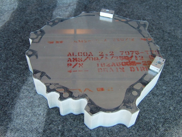
Here's a photo of the aluminum plate after the adapter outline has been machined. The plexiglass template was traced by computer and that data was used to drive a water jet to cut through the thick plate.
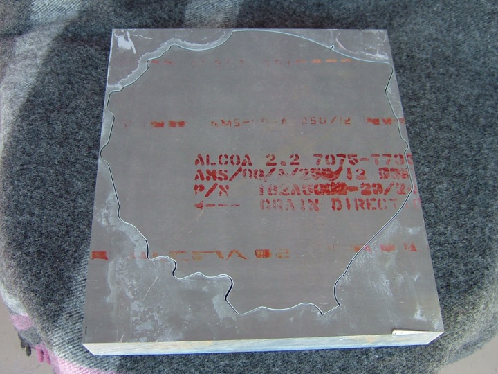 With the part removed from the excess aluminum, you can see the sand blasted finish on the edge from the water jet process. I also really like this photo because of the perfect negative of the template left in the original aluminum plate. How cool is that?
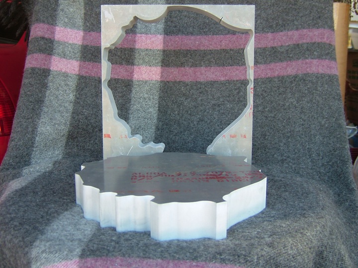 This photo below really shows how well the profile of the transmission bell housing has been replicated. You can also get a sense of how thick the plate still is. A significant amount of material can be removed near the edges (to reduce weight).
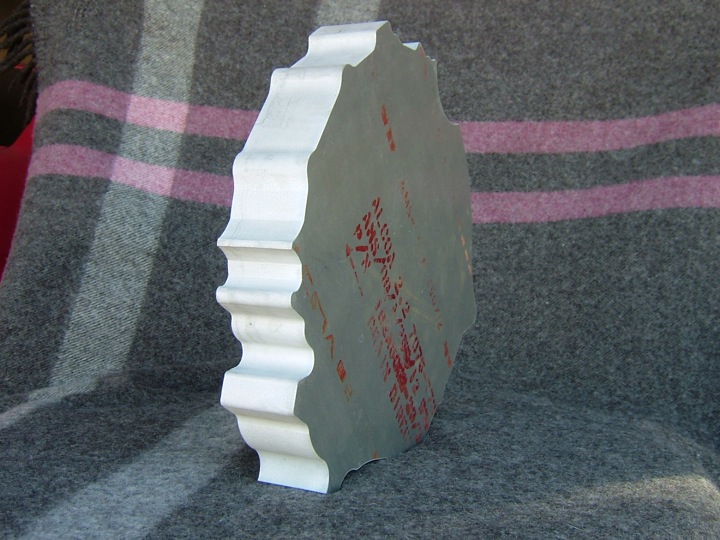 This last photo shows the plexiglass template laid on top of the adapter plate. The template is still necessary to machine several of the adapters features. It allows the 10mm alignment pin holes to be drilled accurately, center can be found from those pin holes using measurements taken earlier, and the bolt holes needed to secure the adapter plate to the transmission flange can be located. So far, so good.