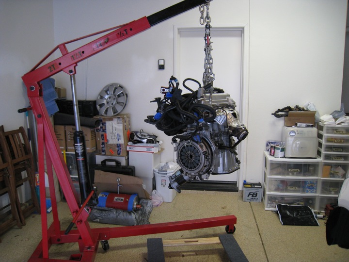
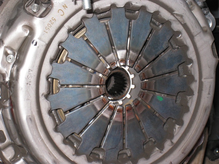
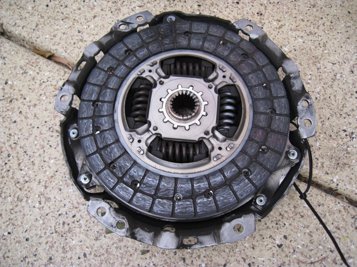
My father (who is an aerospace engineer) stopped by this weekend to help me with the key measurements and dimensions required to design an adapter plate and hub for mounting the Warp 9 electric motor to the flywheel/clutch and ultimately reconnecting it all so that it aligns and drives the transmission as the factory engine would (mechanically). First, we removed the clutch seen below:
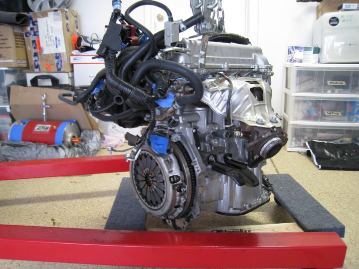
 Below is a shot of the flywheel after removing the clutch assembly.
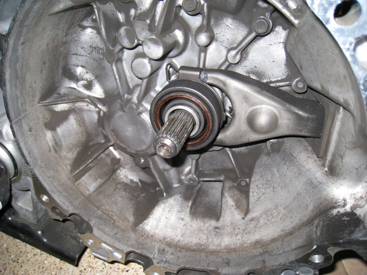
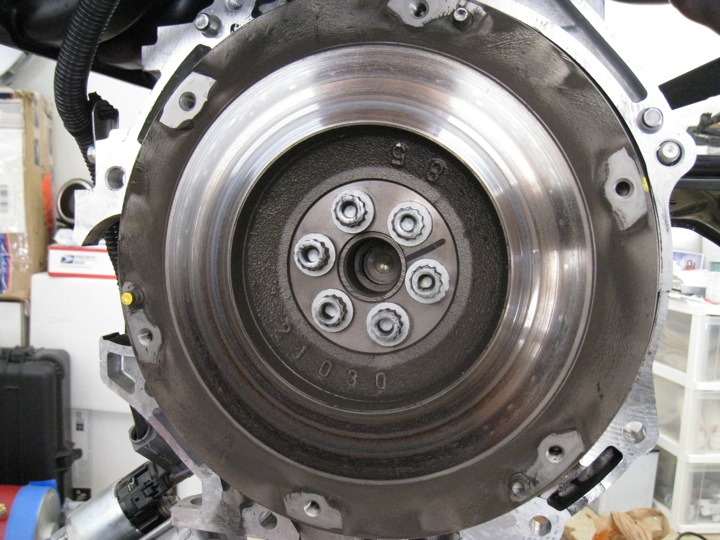 And here is what the block looks like with the flywheel removed. You can see the hub in the center (with 6 bolt holes) that will need to be duplicated in steel for the electric motor to mount to the original clutch and flywheel. The main difference being how it mounts the motor shaft via a slotted keyway. Important measurements focused on the relationship of features from the face of the engine flange to the hub along the axis of rotation. Many measurements were taken many times to ensure accuracy for later machining of the adapter parts.
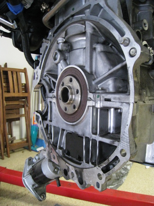 In order to create the adapter plate, my father came up with a scheme to make a very accurate template/tracing of the transmission bell housing flange by trimming a piece of 1/8" plexiglass to match the profile. After a rough trim, we devised a scheme to get the 2 alignment pins represented on the template. This will ultimately allow us to find the center using a few measurements taken from the engine side pins to the center of the hub.
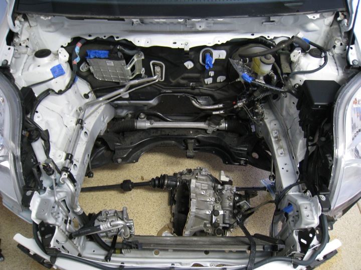
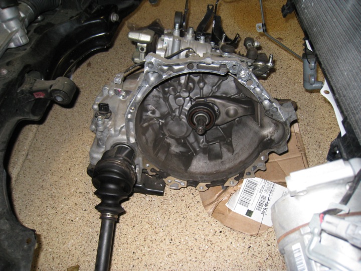
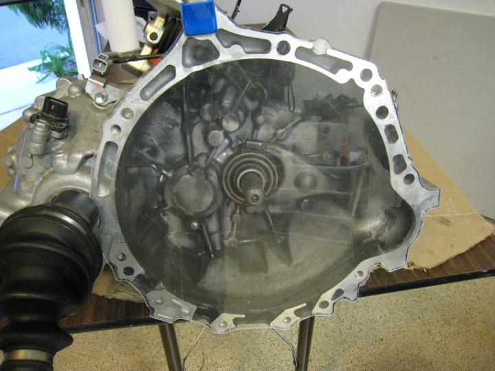 Here's the rough cut clamped to the transmission. What I really like about this idea is that it's rigid but thin material, the transparency makes it simple to se how things line up throughout the process of making it, and it's cheap. The next update will include more information about how this template was completed as well as photos of the finished template.