 I also got my diode and inductor from EVTV. These go with the Chennic DC-DC converter and should make it a more reliable unit.
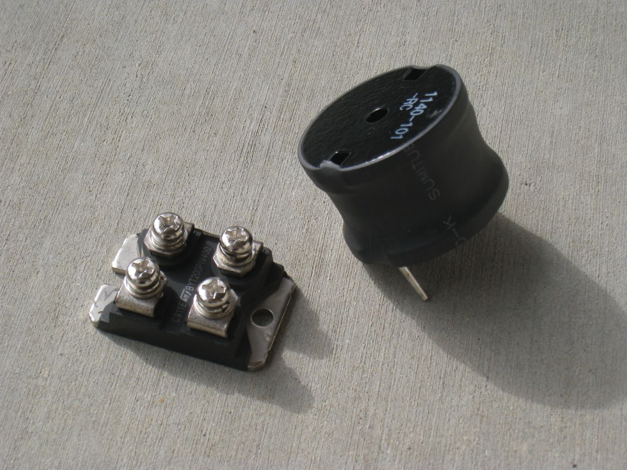 I also got my diode and inductor from EVTV. These go with the Chennic DC-DC converter and should make it a more reliable unit.
 Next up are some bits I received from Jack Rickard and the folks over at EVTV. On the left is a heavy-duty maintenance switch that I will try to install in a convenient place to disconnect the HV battery pack from the equipment under the hood. It's certainly not meant to replace a circuit breaker for emergency disconnects under load, but I'm hoping it can carry 192V across it without any issues. We'll see. On the right is a Chennic 400W DC-DC Converter for supplying the 12V system. A diode and inductor are on the way that should make this a reliable converter. It's a lot smaller than I thought it was going to be. Likewise, the switch was larger than I had expected.
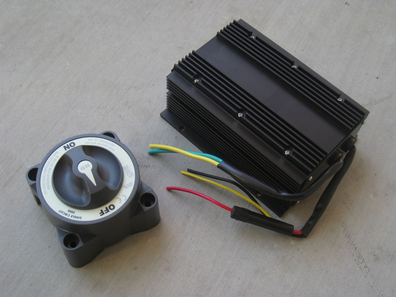
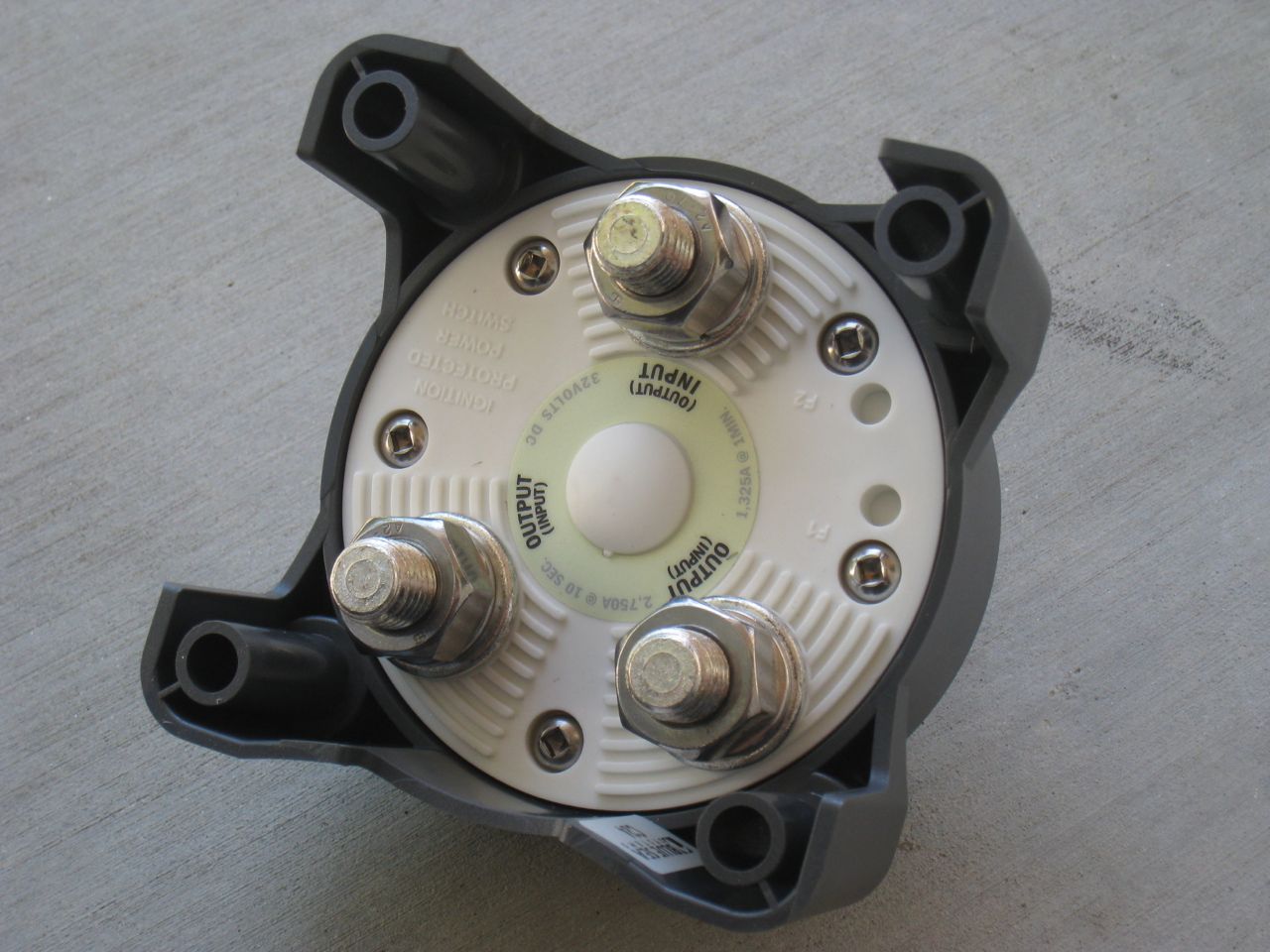 Above you can see the back of the switch. The terminals are beefy enough to accept 4/0 cable and lugs (according to the specs) and the whole assembly feels solid. I'll have to work on some more brackets/mounts to start installing all of these components where I have space under the hood. It's like a great big puzzle.
 I also installed the motor speed sensor today. This little unit is extremely simple to mount and the only real trouble I ran into was to remove a tiny bit of sheet metal from the unibody that interfered with slipping the sensor collar over the commutator shaft. A bit of grinding and things were looking good.
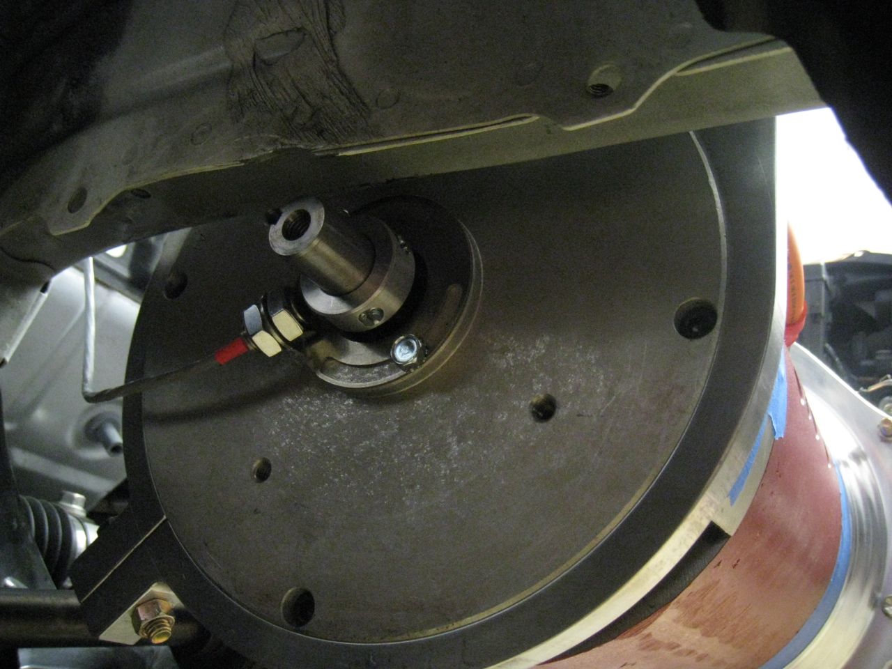
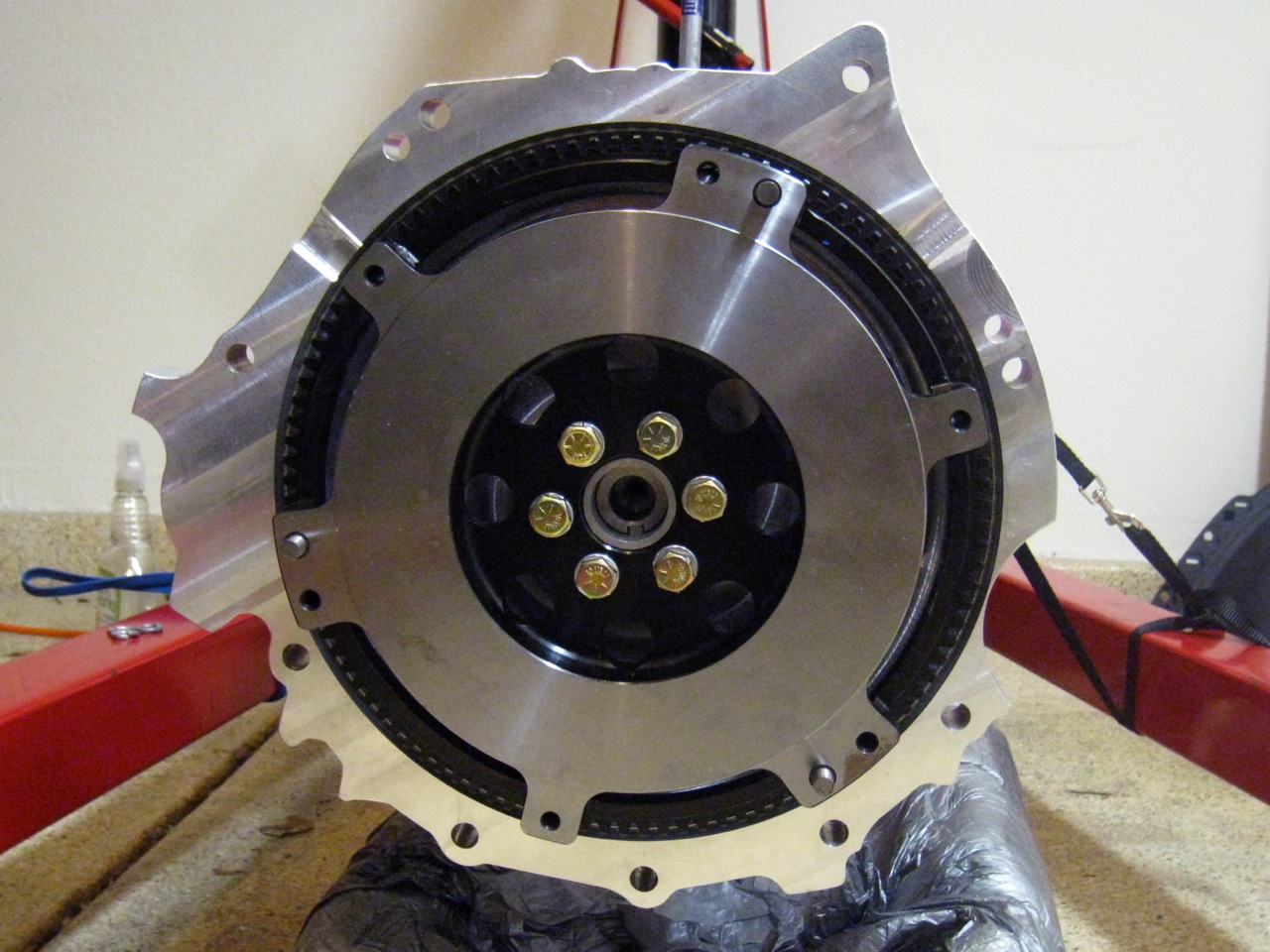
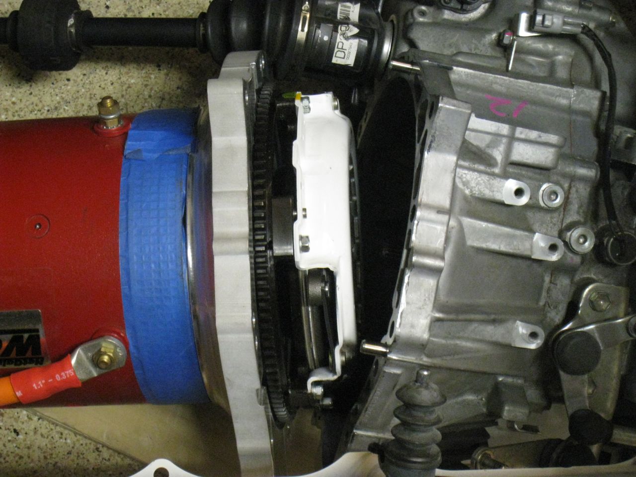 I moved the motor side assembly toward the transaxle and made sure that the input shaft engaged the clutch disc. A quick way to test this is to move the flywheel at this point and check that the driveshafts coming out of the transaxle rotate in accordance. Bringing the two halves together was a tedious process of going around the flange and tightening down all the bolts to torque specs.
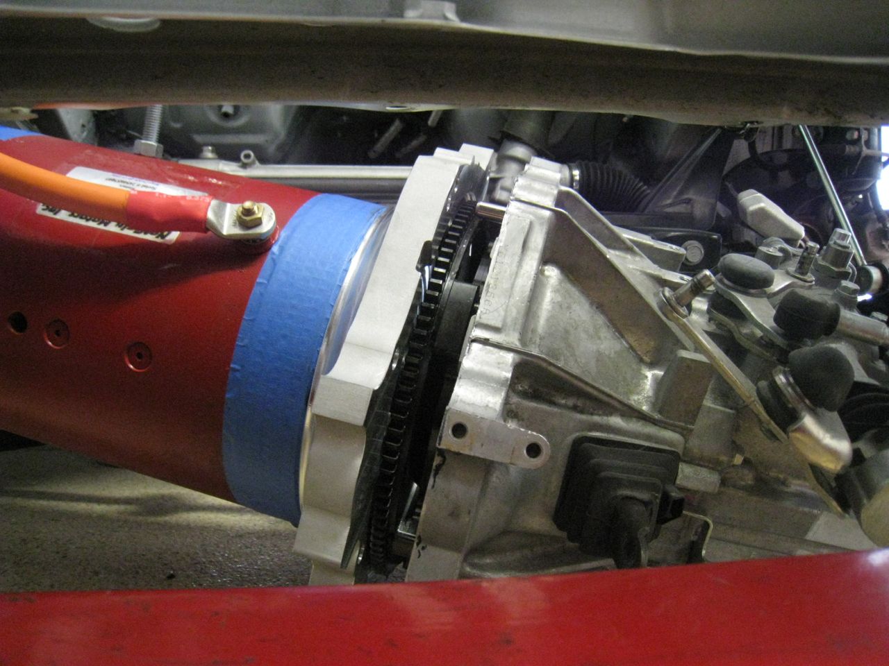 The completed drivetrain assembly was hoisted into position and I proceeded to secure it to the chassis by bolting up the OEM motor mounts and then the tail shaft mount that was custom fabricated. This was another headache from a home-garage-logisitcs perspective, but I managed to get it done (I also managed to hit the windshield in the process and create a crack at the edge…will be replaced). Once everything was verified to be in the right position, I began the process of torquing down all the mount bolts and removing the engine hoist. The next two photos show the drivetrain suspended in the car, finally!
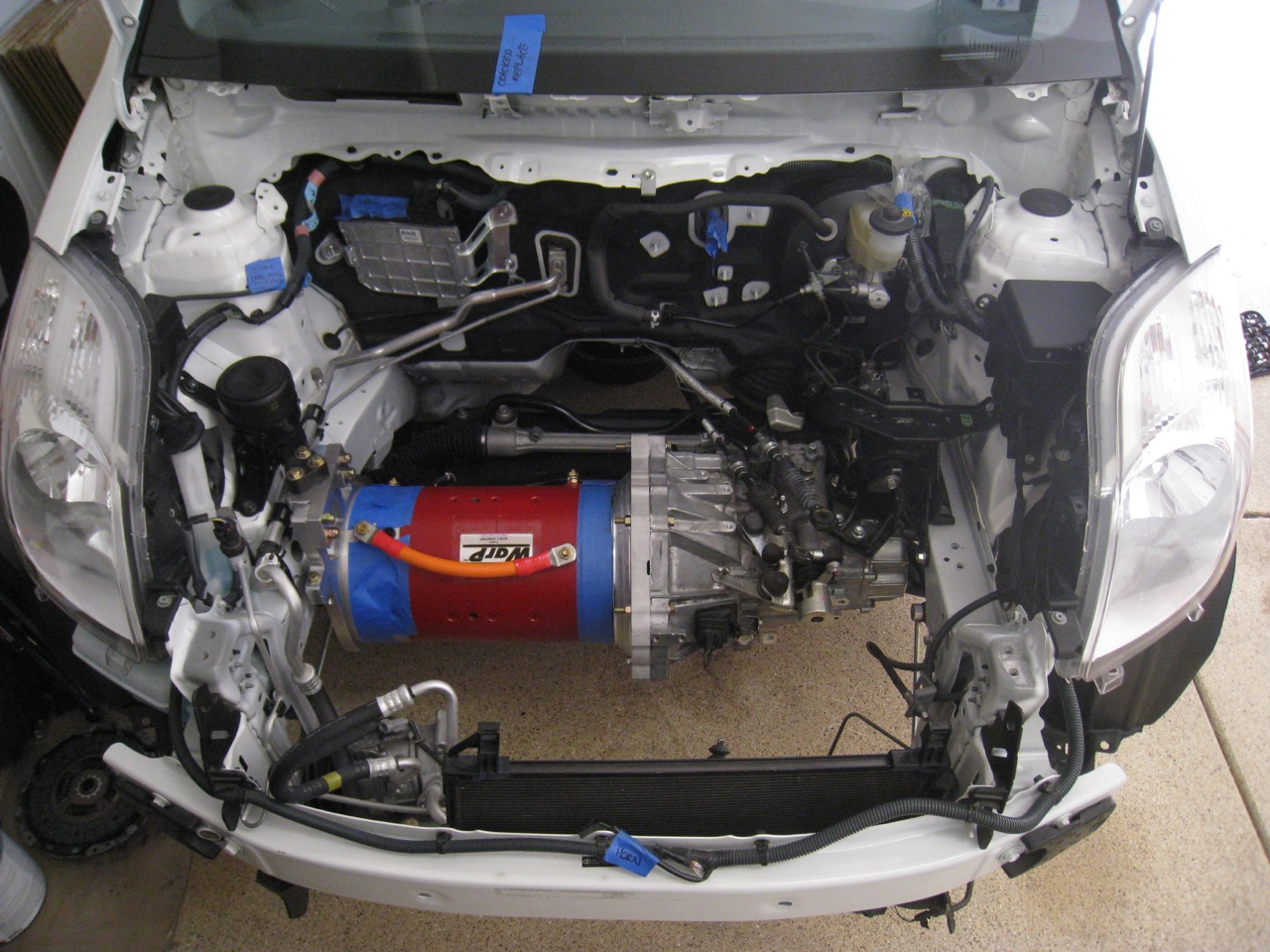
 As you can see it looks really nice mounted in the car and I think the engineering and quality of the machine work paid off. Finally, I went about re-installing all the original equipment and hardware that is needed to shift and operate the clutch. I cleaned up and re-greased all the linkage pivots to ensure really smooth operation. It went together quickly as I took photos of the disassembly, wrote down notes, and also have the repair manual handy. Not to mention, it was pretty straight forward.
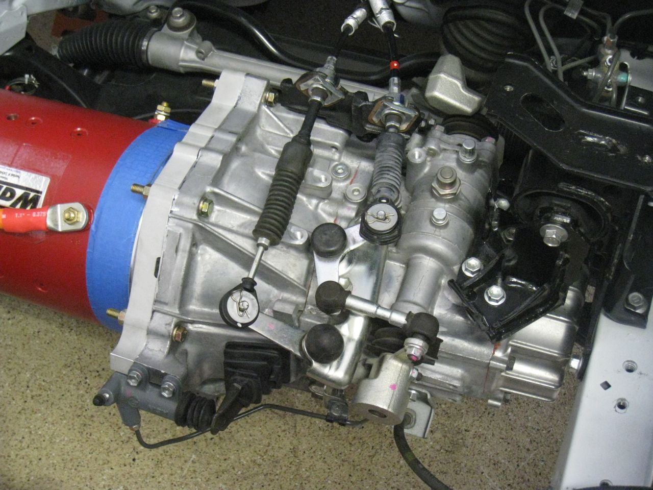
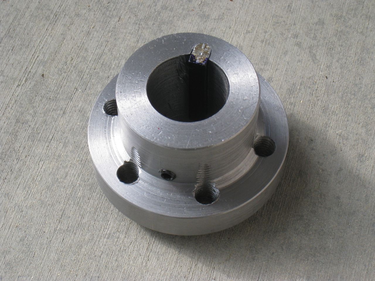
 Installing this piece requires some care and precision as the distance from the face of this part to the face of the transmission adapter flange to ensure a proper engagement of the drivetrain assembly.
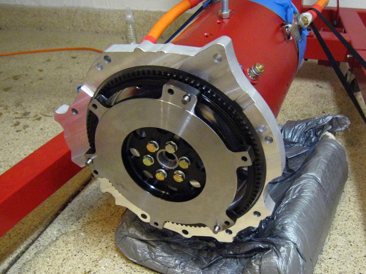 I will try to post a video of the motor spinning up with the flywheel mounted. The balance seems very good at speed although we did notice some small vibration as the motor comes to a stop. The test was only done with a 12V battery so no real power was thrown at it yet. Next step is to take the flywheel off and get it balanced to the clutch before putting it all back together and into the car.
 Installing this piece requires some care and precision as the distance from the face of this part to the face of the transmission adapter flange to ensure a proper engagement of the drivetrain assembly.
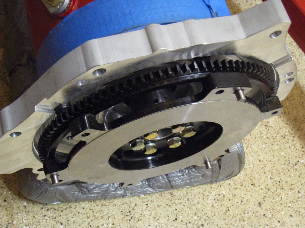
 The cradle portion seen above and below is two-part construction. A top and bottom piece surround the motor with 3 bolts securing the halves together. The blue surface seen in the photos is a marking fluid used during layout and machining (seen previous posts for more info) and is temporary. Below is a photo that shows the bolt locations clearly:
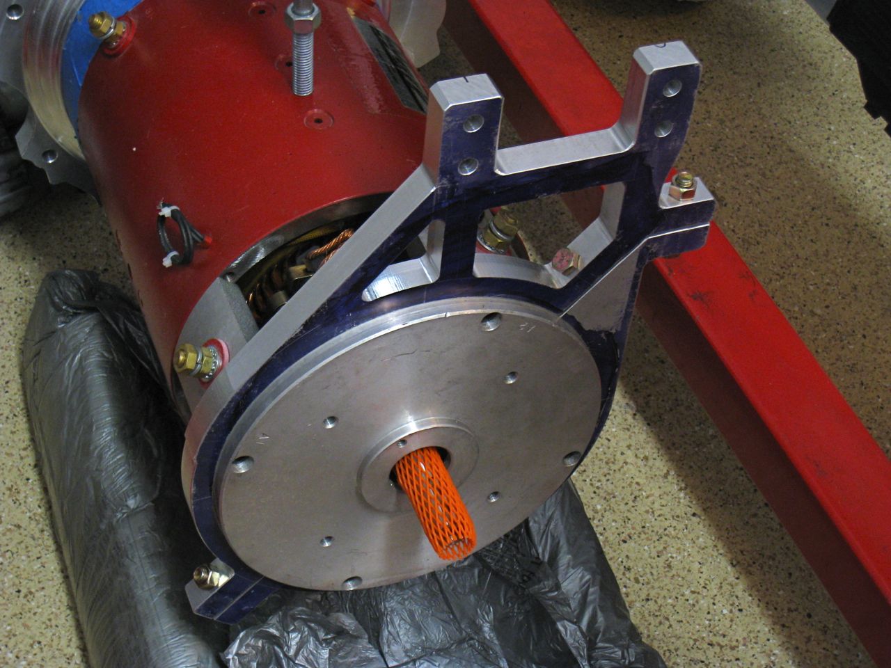
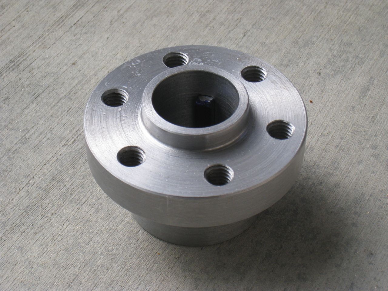
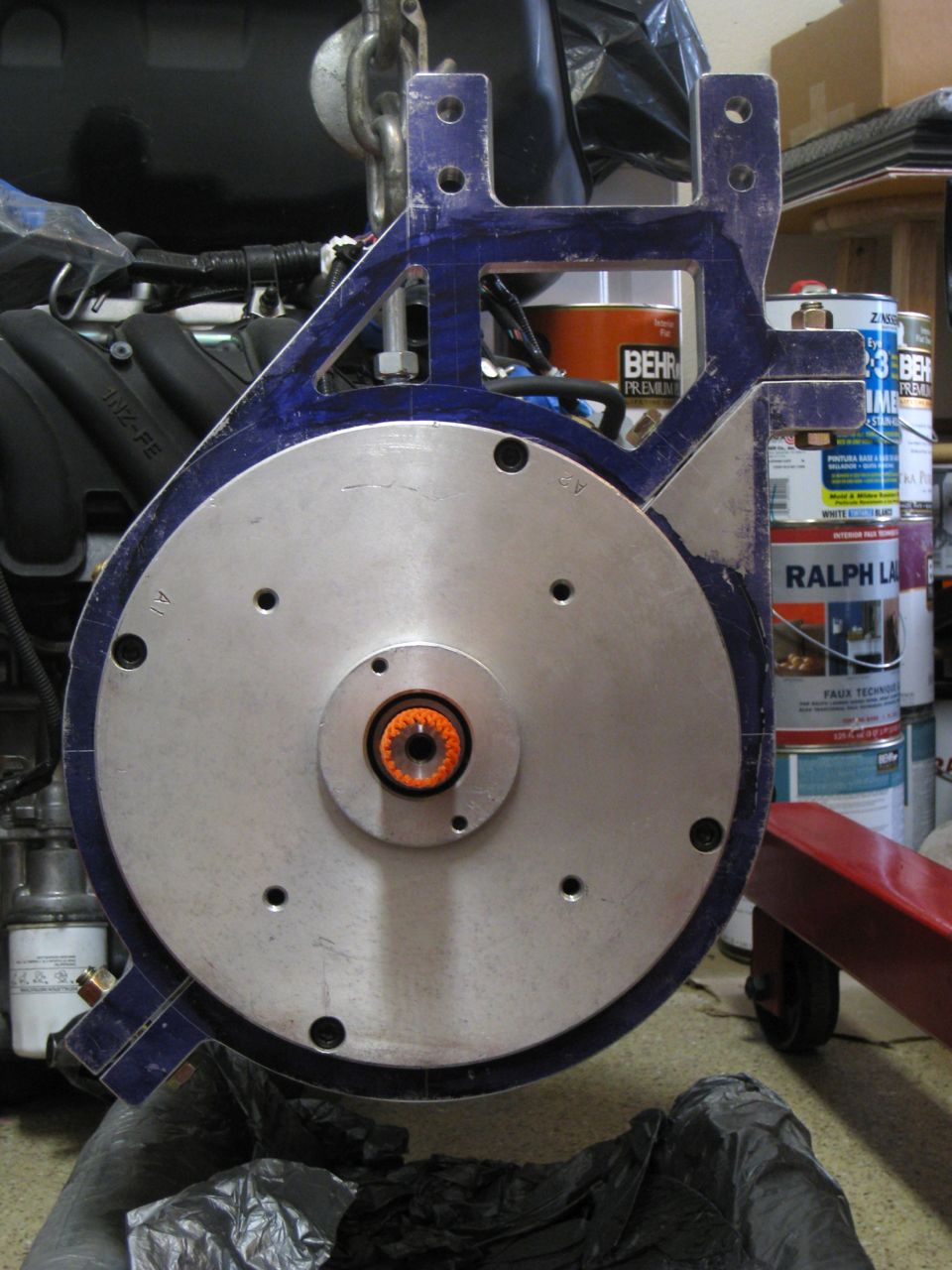
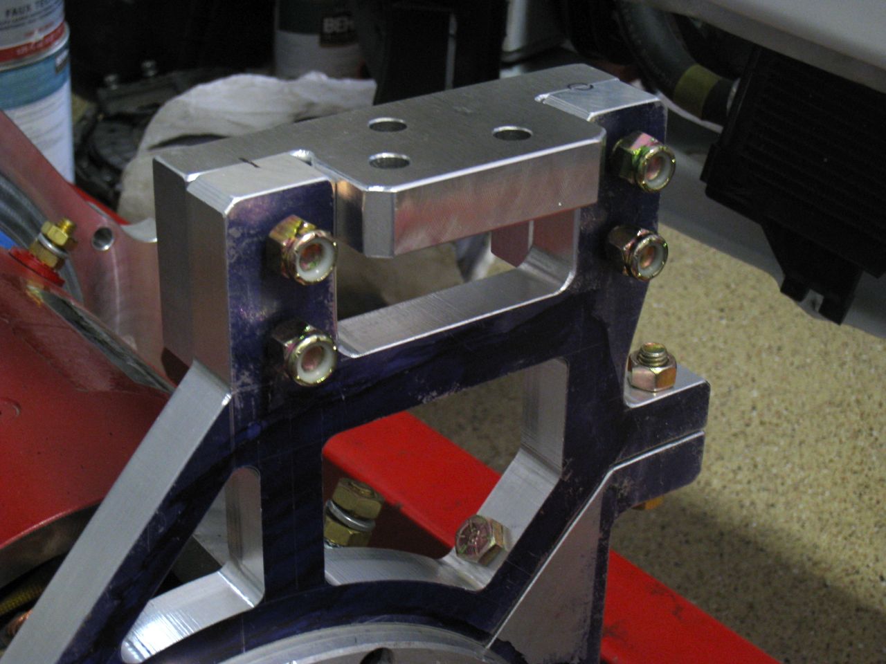 Above you can see the third piece of the aft-mount equation. This part mates the upper half of the cradle with the OEM passenger-side motor mount already in the car. The three holes are used to bolt this entire assembly to that mount and take advantage of the original soft mount design that supported the gas engine.
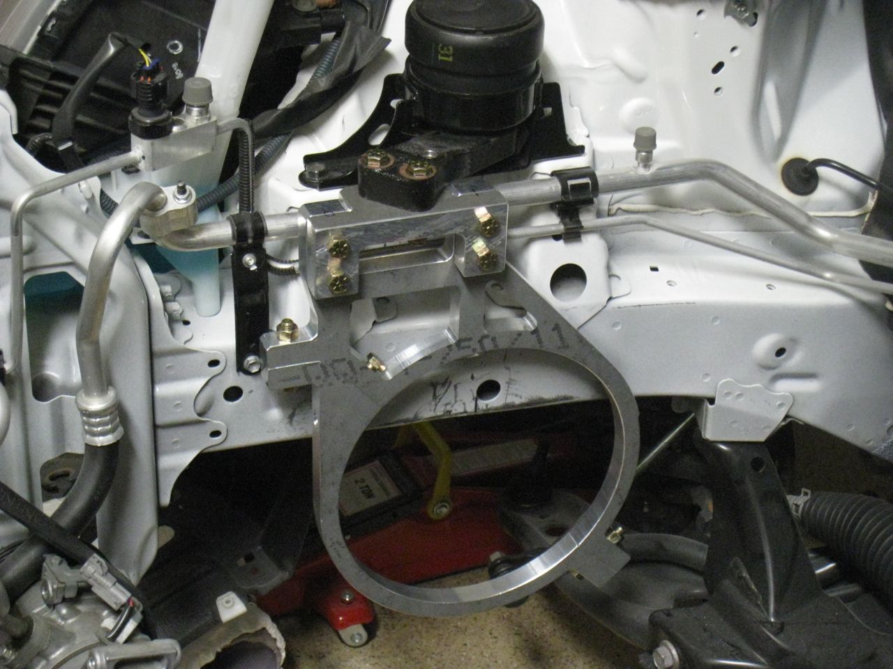 Lastly, here's a look at the mount in the car (without the motor in it). I quickly and loosely bolted everything up one last time just to confirm alignment and fit. It looks like we're in business.