I received an update today. Before final milling and drilling the aluminum plate, we decided to drill a test piece with the locating pin holes and bell housing mounting holes. Luckily, the shop that cut the aluminum plate with the water jet (using the the plexiglass template) tested their computer trace by first cutting it out of thin Masonite.
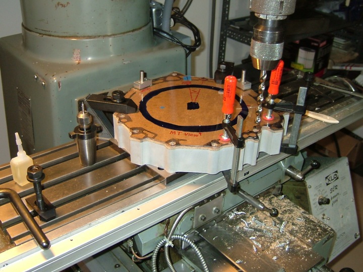 Above you can see the Masonite sandwiched between the 2 inch aluminum blank (bottom) and the plexiglass template we made (top). Below is a closer view:
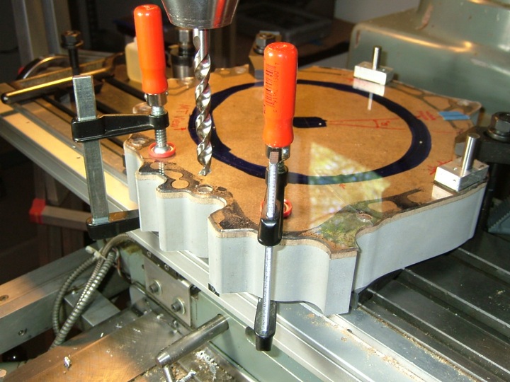 Here is the Masonite test template. You can clearly see the drilled holes. Notes have been made to show the orientation of "top dead center", the diameters of the locating pins are written next to their appropriate locations, and the facing of the template (in this case MT for motor-transaxle) has be written at the bottom.
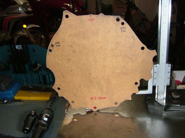
With the locating pin holes and bell housing mounting holes drilled into this rigid piece, I can check the fit. The piece was mailed to me today and should arrive in a few days. Any adjustments (if needed) will be marked up on this piece, mailed back, and then the aluminum plate will be machined to these final specs. We're getting close.
No comments:
Post a Comment