Here are two update photos of the motor-flywheel adapter being machined. This part is being turned on a lathe from a solid piece of 4130 (chrome-moly steel). It will installed on the drive-end motor shaft with and secured using the keyway (and probably a set screw to really keep it secure). Six holes will be drilled into the face so that the flywheel/clutch assembly can be attached the same way it did on the gas engine.
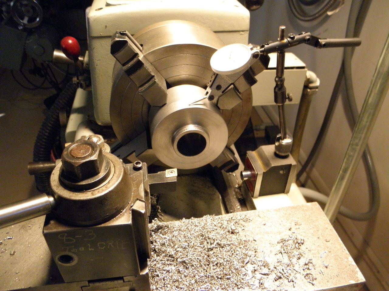
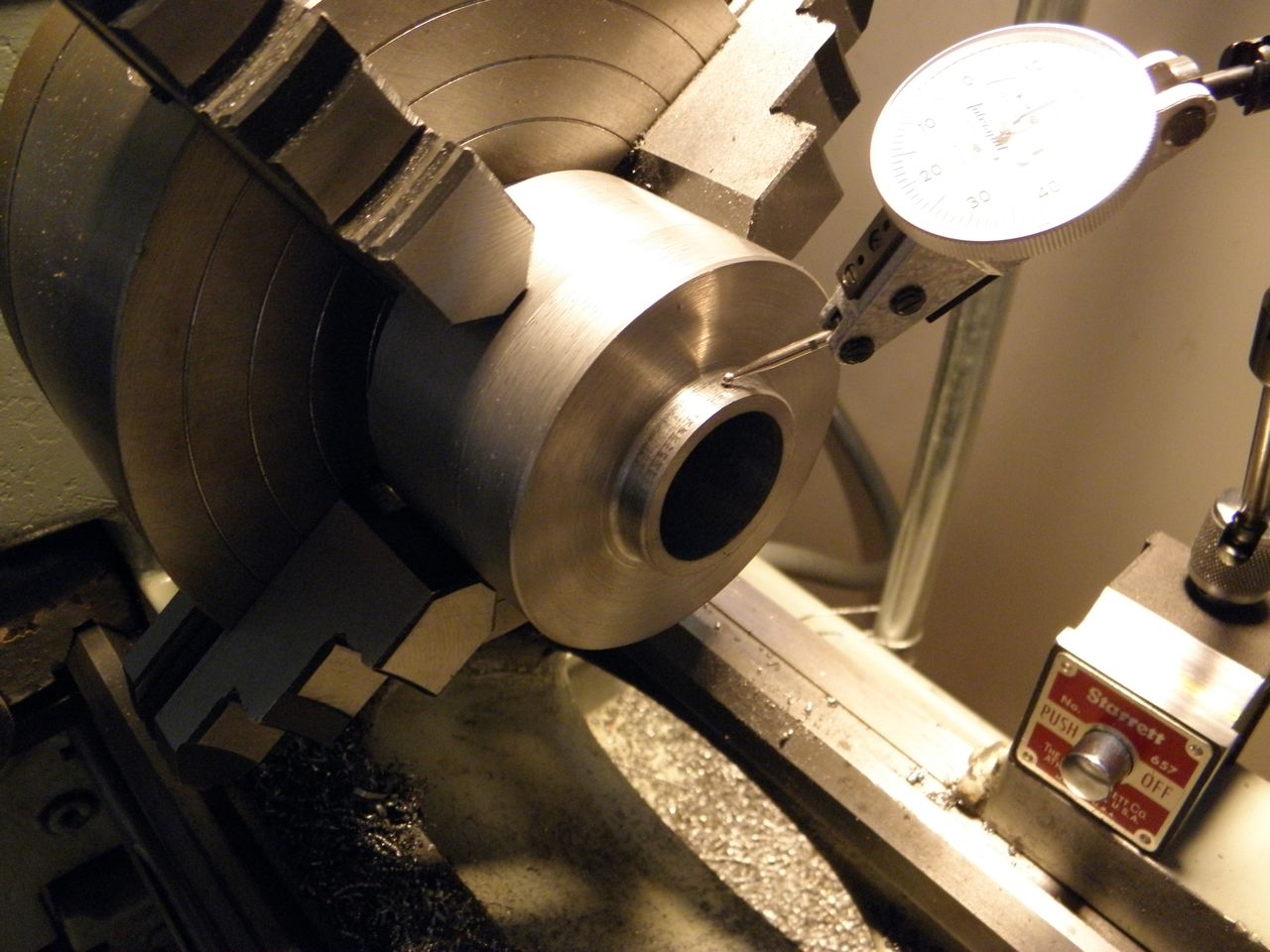
Above you can see a dial indicator which can be used to ensure a surface is within allowable tolerances as it rotates. It's critical that the face of this part be square to the center line of the motor shaft so that the flywheel will not wobble as it rotates.
Below is the aft-motor mount being fabricated. This will support the commutator end of the motor and bolts up to one of the OEM motor mounts already in the car. It's going to be made from multiple pieces. Here are the two largest pieces being milled as a single piece to be split at the end so that the two halves can be installed around the motor in a cradle-like configuration.
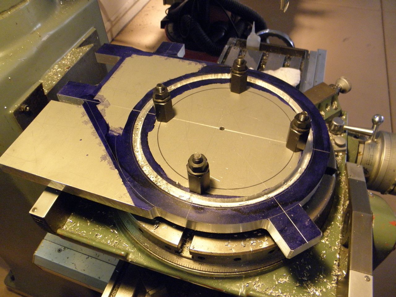
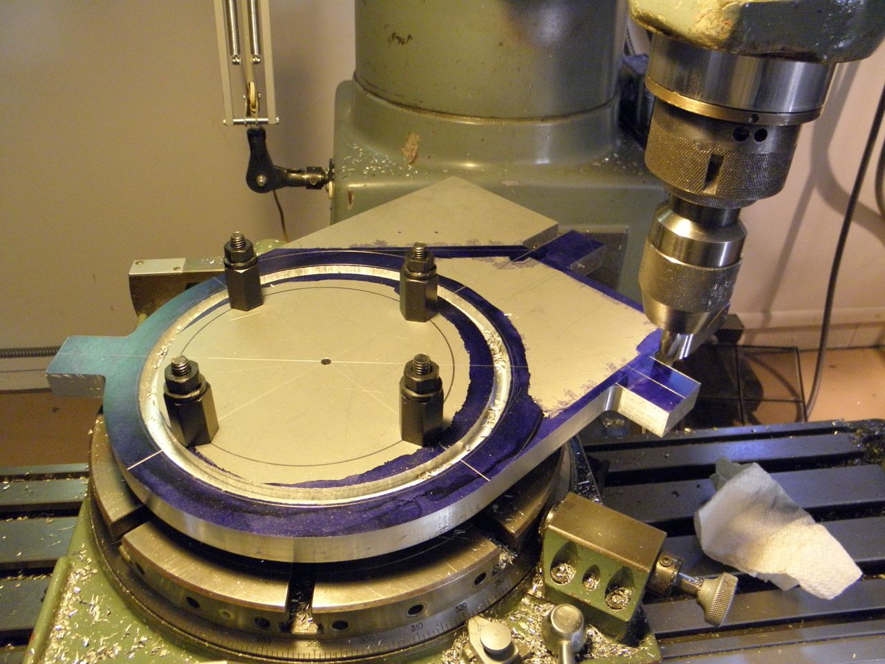
A third piece is needed to connect the cradle plate seen above to the OEM motor mount. This piece is in essence an adapter and many measurements were take to ensure that the geometry of these parts would result in a shaft alignment that matched the original gas engine. With these parts completed, the mechanical drive-train will be complete. Back to cutting up the car!
No comments:
Post a Comment